Viaduct Model — Water Corridor

MMC-VD — 1×1

1 leg · 1 level · W, FB, P, SR

The finger viaduct — the lightest structure in the MMC family. A services-only deployment: no freight, no maglev, no HVDC arms. The structural sizing is governed by water pipe weight, wind load, and seismic — all substantially smaller than the multi-service governing cases for MMC-VA, MMC-VB, or MMC-VC.

The lightest structure in the MMC viaduct family. A single central pylon carries a single platform-level deck supporting four services: a water pipe (the primary load), a power line for source-end and in-line pumping, a service rail for inspection and supply movement during operations — and during construction, the rail is the build mechanism itself. The viaduct extends itself outward along the corridor, span by span, off the live deck behind it. MMC-VD is the workhorse of the Sovereign Aqueduct Network water-capture programme — the finger viaducts that reach from the MMC-VA continental main aqueduct outward to individual northern river catchments.

MMC-VD at a glance.

ConfigurationSingle-leg, single-level finger viaduct
Legs per pylon1 — single central leg
Pylon spacing25 m — 40 pylons per kilometre
Deck heightVariable — matches the MMC-VC tapered segment family; typical 8–20 m above ground
Span25 m — same as MMC-VC and MMC-VB
Foundation1 × 4 m OD ATS caisson, 10 m planning depth, ~10 ring segments + 1 anchor cap per pylon
Cutter head1 per pylon — sacrificial hybrid, stays in ground as permanent PT anchor
Tubular1 × 7″ × 29 ppf L80 13Cr API 5CT — sized for the lighter single-leg water-corridor load case; reduced diameter from MMC-VC's 13.375″, 13Cr alloy retained for material-family commonality across the MMC platform
ColumnP1 tapered segments, single leg, same Megafactory family — 2 segments per pylon for typical 8 m height; more for taller deployments
Transverse cap beamPrecast concrete crossbeam atop each pylon, perpendicular to corridor axis, with integrated saddles for water pipe, service rail, and services trough via P#7 rib — 1 per pylon
Platform deckSingle P#7 precast concrete module per 25 m span, sitting on the transverse cap beams of adjacent pylons
Deck servicesWater pipe (diameter project-specific), service rail, power line, fibre & SCADA conduit, transmission and ancillary service trough
Self-building deploymentYes — the service rail is the construction mechanism. The viaduct extends itself span by span along the corridor.
Megafactory familyStrict subset of MMC-VC modules — same caisson rings, same column segments, same Megafactory production line

How MMC-VD is built on the platform.

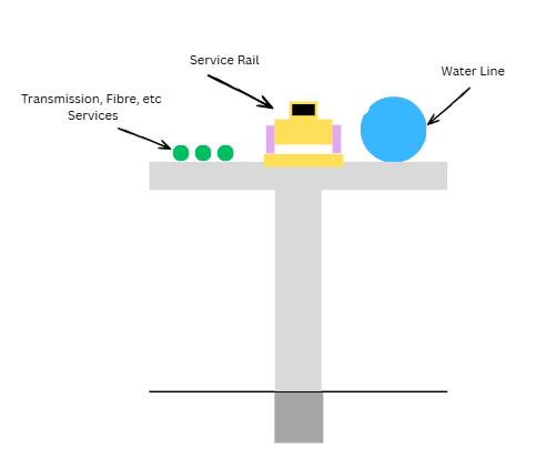
MMC-VD is the lightest expression of the MMC platform. The structure is single-purpose — built to carry water and its supporting services, nothing else. No freight, no maglev, no HVDC arms, no hyperloop reservation. The structural sizing is governed by the water pipe weight, wind load, and seismic — all substantially smaller than the multi-service governing cases for MMC-VA, MMC-VB, or MMC-VC. The result is the smallest pylon, the shallowest foundation requirement, and the lowest per-kilometre cost in the MMC structure catalogue.

MMC-VD's economic argument rests on its position as a strict subset of MMC-VC and below. The Megafactory is dimensioned for Phase 0 MMC-VB; the establishment cost is paid by Phase 0. MMC-VD modules are a strict subset of MMC-VC modules — same caisson rings, same column segments, same anchor caps, same tubular. MMC-VD production is incremental on a factory already running. The Sovereign Aqueduct Network deployment (1,500–3,000 km of MMC-VD across SBC #3 and SBC #5 northern catchment corridors) is absorbed by the same production lines that run for MMC-VC and MMC-VB.

The self-building deployment is the defining install advantage. As the viaduct advances from the MMC-VA junction outward along the corridor, a service train works from the deck of the already-built section: drill the next foundation, set the next pylon, lift the next deck module, lay the next length of service rail, advance the train onto the freshly-laid rail. Each cycle adds one pylon span and lays the rail that the next cycle works from. The same service train, after the viaduct enters service, becomes the operations-phase rolling stock — carrying inspection personnel, maintenance crews, and component replacements along the length of the corridor.

Where MMC-VD is deployed.

MMC-VD is deployed wherever the Sovereign Aqueduct Network requires a finger to reach a water source or wherever last-mile water delivery is needed. The continental water-capture programme captures monsoon water from multiple distributed river catchments; each catchment needs its own finger viaduct reaching from the MMC-VA continental trunk into the source. The fingers fanning out from the main corridor on the published Sovereign Aqueduct Network maps are MMC-VD deployments.

SBC #5 Top End northern catchments. Multiple MMC-VD fingers fanning out from the MMC-VA Top End corridor to reach Cape York Peninsula and Arnhem Land river systems — the primary northern monsoon catchment zone.
SBC #3 Gulf Coast catchments. Further MMC-VD fingers reaching the Gulf of Carpentaria river systems off the Gulf Coast trunk.
Last-mile Water delivery branches. Shorter MMC-VD branches delivering water from the corridor into agrivoltaic zones, AI campus interfaces, and corridor town reticulation networks.
Aggregate Programme-scale deployment. 1,500–3,000 km of MMC-VD finger viaduct expected across the continental programme — the workhorse of the water-capture network.

Companion documents.

The engineering of MMC-VD is documented alongside the rest of the MMC platform memo series. The Models page is the catalogue — the Library is the engineering depth — the Costs page is the unit-rate cost engineering.

In Prep MMC-VD Finger Viaduct Engineering. Self-building progressive deployment methodology, single-leg single-level structural sizing, water-pipe support saddles via P#7 rib, service rail dual-use (construction mechanism plus operations rolling stock). Pending release
Costs MMC-VD Cost. Per-kilometre cost engineering for the finger viaduct — Materials & Foundation, Topside, Install.
Library MMC-VB and MMC-VC Viaduct Engineering. The companion engineering memo for the single-leg viaduct family. MMC-VD modules are a strict subset of MMC-VC modules.

The structure.

MMC-VD cross-section: single-leg pylon supporting a deck carrying transmission and fibre services on the left, a yellow-cased service rail in the centre, and a blue water line on the right. Below the deck the single pylon descends to a ground-level cap and the caisson foundation continues below ground.
MMC-VD cross-section — single-leg single-level finger viaduct. The platform deck carries transmission and fibre services (left), the service rail (centre), and the water pipe (right). Pre-feasibility illustration; engineering renders in production.

MMC-VD on the MMC Patent Family.

MMC-VD is covered by the Architectural Framework (Patent 4) and the single-leg topside configurations referenced in Patent 6. The single-level finger viaduct architecture leverages the same renewable tubular tension element as MMC-VC, sized down to the lighter water-corridor load case — one 7″ tubular per pylon, one anchor receptacle in the cutter head, one tensioning operation at the pylon cap. The self-building deployment methodology — where the service rail on the deck is also the construction mechanism — emerges directly from Patent 4's modular precast pylon segment architecture combined with the corridor-as-its-own-supply-chain principle described in Memo 6 (Build).

View the MMC Patent Family →