Every Multi-Modal Corridors deployment is a combination — one option from each axis. The same productised infrastructure produces every combination through the same Mega Factory Method (per the Manufacturing page); the configuration determines what the deployment looks like at the topside.
Distribution Pole
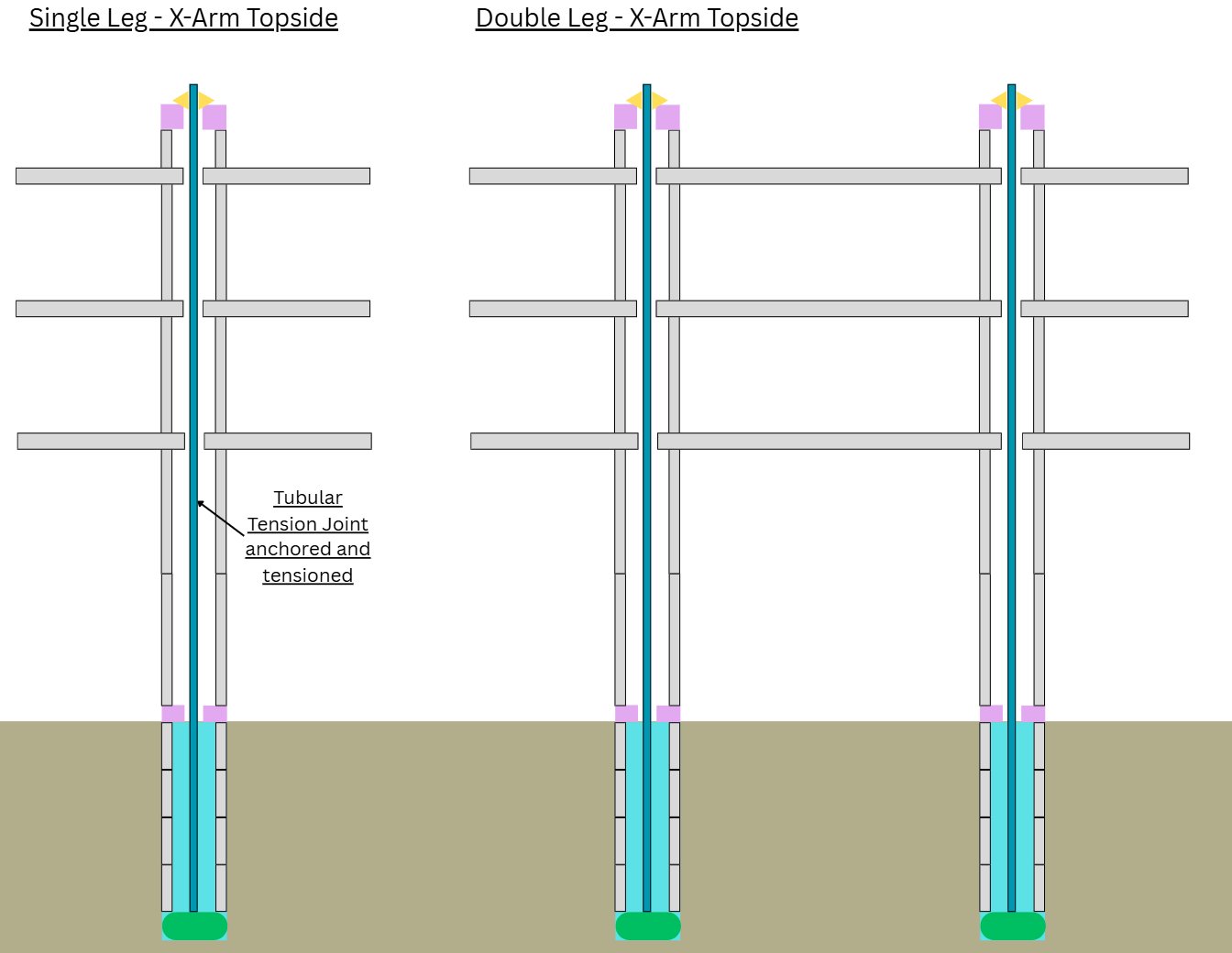
ATS → Single-Leg → Cross-Arm Topside
Replaces wooden distribution poles. Extended operational life, fire resistance, dielectric pylon material simplifying insulator architecture. Scale-appropriate small-diameter pylon segments.
Transmission Tower
ATS → Single-Leg → Cross-Arm Topside
Replaces steel lattice transmission towers across the full voltage range from 66 kV to 765 kV+, including HVDC at ±800 kV and ±1100 kV. Multi-circuit cross-arm configurations engineered for clearance and electromagnetic compatibility. Single pylon covers approximately 80% of continental transmission deployment range.
Dual-Tower Transmission Line
ATS → Two-Leg → Portal Cross-Arm Topside
Two standard MMC pylons coupled by three transverse cross-beams captured through both pylon stacks, forming a portal frame with moment continuity. Used for high-voltage strain towers, river crossings, and heavy conductor loading where a single pylon's capacity is exceeded. Both pylons are the same standard 4m base production unit — no bespoke fabrication required.
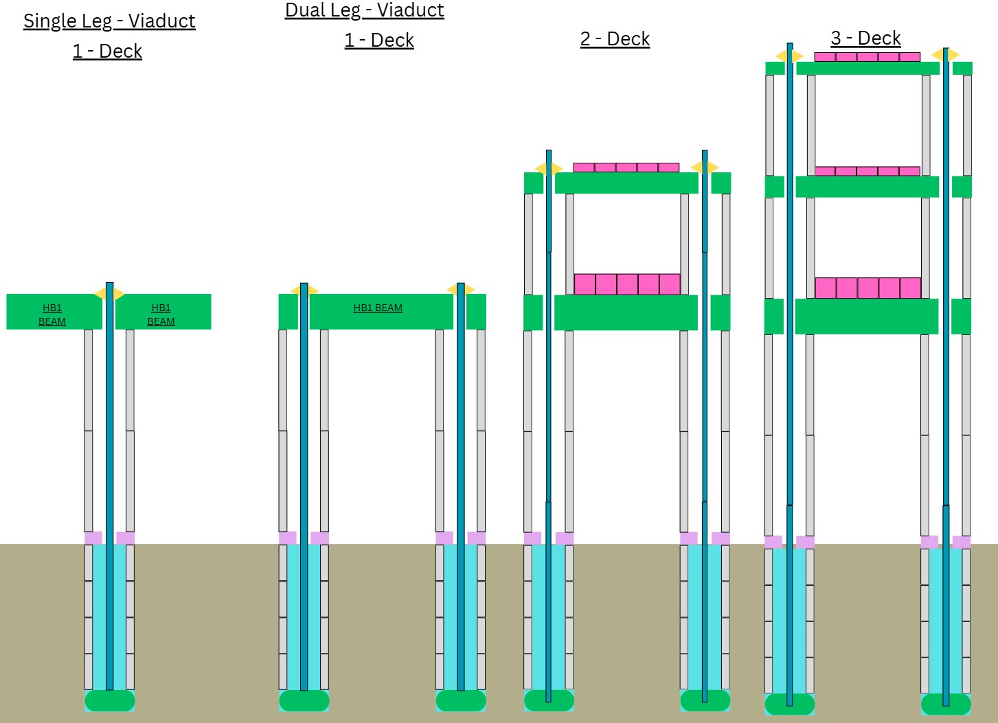
Single-Service Viaduct (e.g. Road or Rail Corridor)
ATS → Two-Leg → Single-Deck Viaduct
A dedicated road or rail corridor deployed as a single-service elevated viaduct. Foundation, structural primitives, and construction methodology identical to multi-modal deployments — only the topside is configured for the specific service. Future service slots remain structurally available for activation without additional civil works.
Multi-Modal Continental Corridor
ATS → Two-Leg → Multi-Deck Multi-Service Viaduct
The headline configuration. Carries the full service combination — passenger maglev, electrified freight, HVDC transmission, water, gas, fibre, hyperloop reservation, road, service rail — on a single elevated structure. Multiple decks at engineered heights, with service slots reserved structurally for future technologies.
Communications Tower
ATS → Single-Leg → Cross-Arm Topside
Same architecture as transmission, with cross-arm configuration adapted for antenna mounting, dish placement, and communication equipment. Ornamental pylon cap or head accommodating top-mounted antennas.