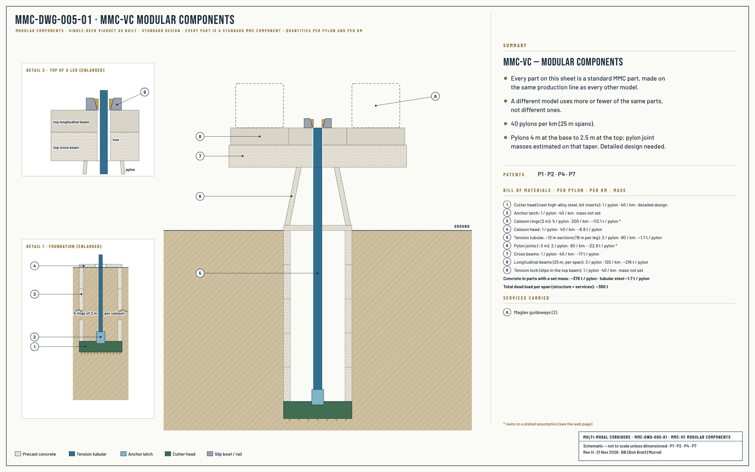
Single leg, single deck: the maglev passenger line. The smallest build of the standard system. Every part is a standard MMC part, made on the same line as every other model. The sheet points to each one; the table counts them per pylon and per km.
Numbers 1–9 are the structural parts; letters are the services this build carries. Details 1 and 2 enlarge the foundation and the top of a leg. Select the sheet to open it full size.
Quantities
The parts list.
40 pylons per km (25 m spans). Numbers match the callouts on the sheet.
Mass not yet set: cutter head, anchor latch, tension lock; maglev guideways
Precast modules, all types (published)
~800
~20
Expansion packers and centralisers are fitted as each foundation needs and are not counted per km.
The MM Lines
Services this build carries.
Each service adds its own parts on the same structure. Per km of corridor.
Ref.
Service part
Per km
A
Maglev guideways (2)
2 track-kmA; 80 guideway segments of 25 mA
Service letters on the page list every service; the sheet letters only those drawn.
Basis
Assumptions.
Unmarked figures are the model page's own, multiplied out. Values marked A rest on:
25 m span, so 40 pylons per km; standard heights, flat ground.
Maglev: two guideways, one segment per span. Freight: three tracks, fastenings at 0.6 m, overhead-line portals every second pylon.
HVDC: one insulator string per pole at every pylon; six sub-conductors per pole bundle. Pipes: ~12 m lengths, one support per span.
Pylon joints ~3 m (from MMC-VC: 2 segments for 6 m); counts are worked out from the heights on the 002 sheets.
Tension tubular per leg = caisson depth + height to the top of the structure, in whole ~12 m sections (12 m confirmed by Brett, 9 Nov 2026).
Caisson rings are 2.0 m tall (ruling 9 Nov 2026). Rings per caisson = planning depth ÷ 2, rounded up: VC 10 m → 5, VB 15 m → 8, VA 20 m → 10, VD 20 m → 10 (depth assumed as VA), towers 10 m → 5. Caisson depth depends on soil, rock and load and is confirmed by geotechnical study, so every ring count is provisional.
Services per span (dead load only, no trains): freight rail 3 tracks × 2 rails × 25 m at 60 kg/m = ~9 t; HVDC 8 poles × 6 sub-conductors × 25 m at ~2.5 kg/m = ~3 t; gas pipe 750 mm, 15.9 mm wall = ~7 t; water pipe 1 m, 12 mm wall = ~8 t and its water ~20 t (VB); fibre ~1 t. VA water: full-bay channel 6.4 m deep × 16.4 m wide × 25 m = ~2,624 t (replaces the published 4,250 t). VA channel wall panels: size, number and mass to detailed design, not included in the dead load.
Masses from geometry, reinforced concrete at 2.5 t/m³. Caisson ring 4.0 m OD, 0.4 m wall, 2.0 m tall: ~22.6 t. Caisson head 4.0 m OD, 1 m hole, 0.3 m thick: ~8.8 t. Teeth and grout not included.
Pylon joints (ruling 10 Nov 2026): ~3 m each; every pylon 4.0 m outside diameter at the base (the caisson width) tapering to 2.5 m at its top, whatever its height. Wall taken as 300 mm at the base, thinning 100 mm per 99 m. Masses are estimated on that taper; detailed design is needed.
Tubular: 20 in × 171 ppf = ~254 kg/m (VC: 13-3/8 in × 72 ppf = ~107 kg/m), per the model pages.
Cross beams: memo masses. VC HB1 ~17 t; VB HB1 ~43 t, HB3 ~29 t; VA HB1–HB5 ~65, 65, 43, 43 and 29 t (Big Bertha memo); VD by analogy ~43 (freight), ~43 (services deck, as VA HB3) and ~29 t (maglev), assumed. Transmission cross-arms and cross-beams: not set.
Longitudinal beams: estimate on Super-T proportions (1,000 mm deep for spans to 25 m; 100 mm webs; 240 mm base), widened to a flush 3.4 m unit: 180 mm top flange forming the deck, two 100 mm webs, a 1.2 m × 240 mm bottom flange, 1 m solid at each end: ~1.08 m² of concrete, ~72 t per 25 m beam. VA aqueduct level taken the same (its load is heavier; not yet sized).
Cutter head: cast high-alloy steel with bit inserts; mass is not a design driver and is left to detailed design.
 Maglev guideways (2)


