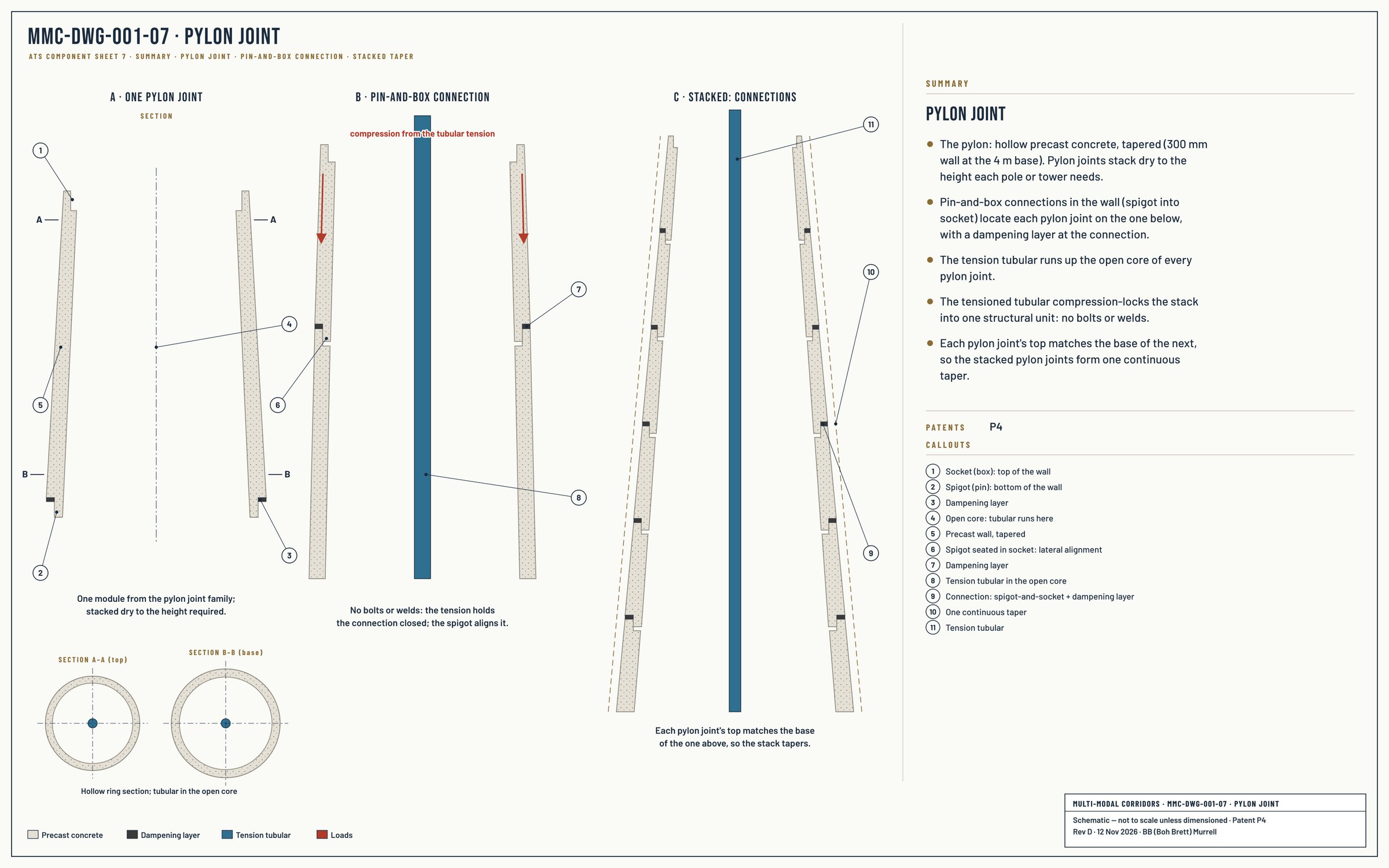
The visible pylon — the structural column rising from the foundation to the topside — is assembled from modular precast concrete segments stacked vertically. Each segment is factory-cast to engineered geometry, with pin-and-box joint detail providing positive lateral alignment between adjacent segments. The segments are not bonded by mortar, post-tensioning ducts, or in-situ concrete; they are held together by the tensioned tubular passing through the centre of every segment.
Design
Modular precast segments, captured by tension.
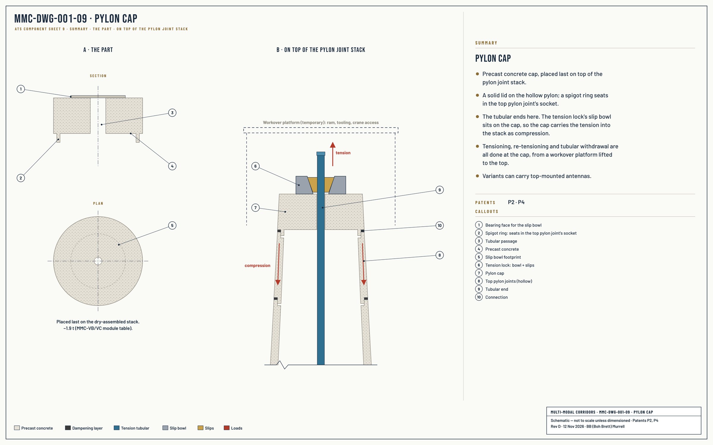
MMC-DWG-001-07 · Pylon Joint. Hollow tapered segments, spigot-and-socket joints with a dampening layer, stacked to one continuous taper. Summary sheet, Rev D. Select to enlarge.MMC-DWG-001-09 · Pylon Cap. Placed last; the tubular ends here and the tension lock bears on it. Summary sheet, Rev D. Select to enlarge.
The factory-cast modular approach is the productisation backbone of the platform. The same precast factory produces segments for distribution-pole-scale deployments, transmission-tower-scale deployments, and continental viaduct deployments — varying segment diameter, height, and topside fitting per the configurator while the manufacturing system itself stays constant. See the Mega Factory Method →
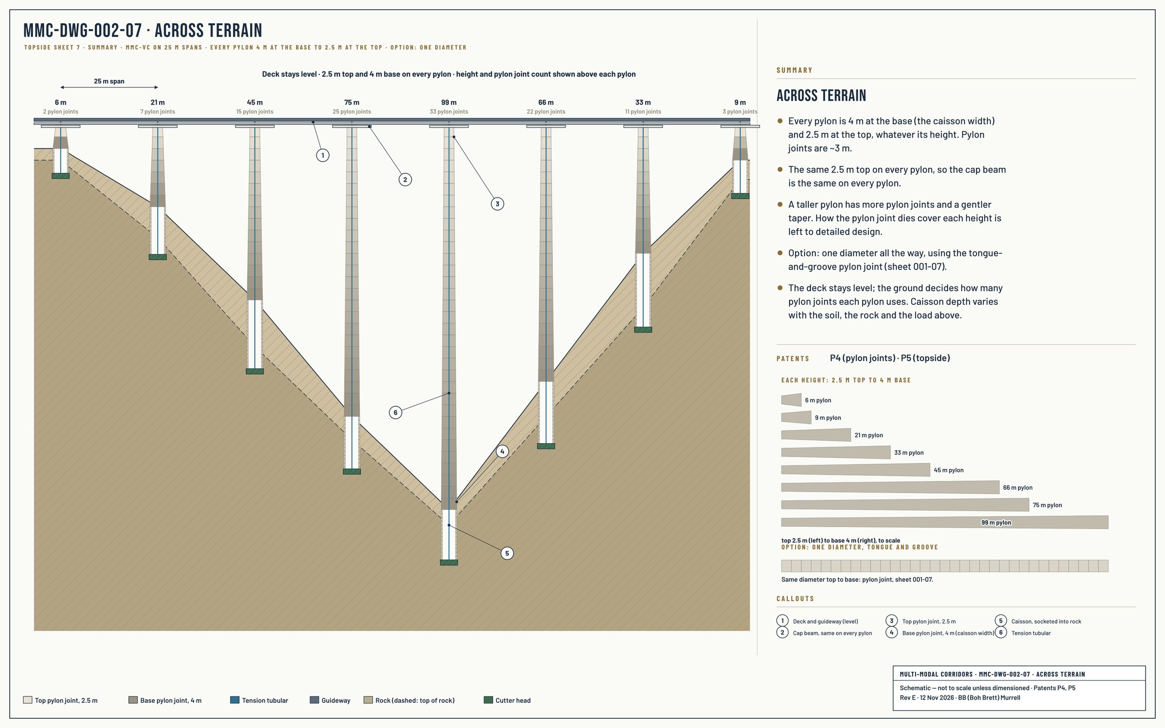
MMC-DWG-002-07 · Across Terrain. Every pylon 4 m at the base to 2.5 m at the top; detailed design needed. Option: one diameter, using the tongue-and-groove pylon joint (001-07). Summary sheet, Rev E. Select to enlarge.
Technologies
Tension tubular, connections, tension lock.
Tension tubular
The tubular itself is sourced from oilfield service inventory. Oilfield tubulars are manufactured to standardised dimensions, threaded connections, and material specifications, with global manufacturing capacity measured in millions of metres per year. The ATS uses standard oilfield tubular sizes — sized for ATS load requirements — within proven manufacturing categories.
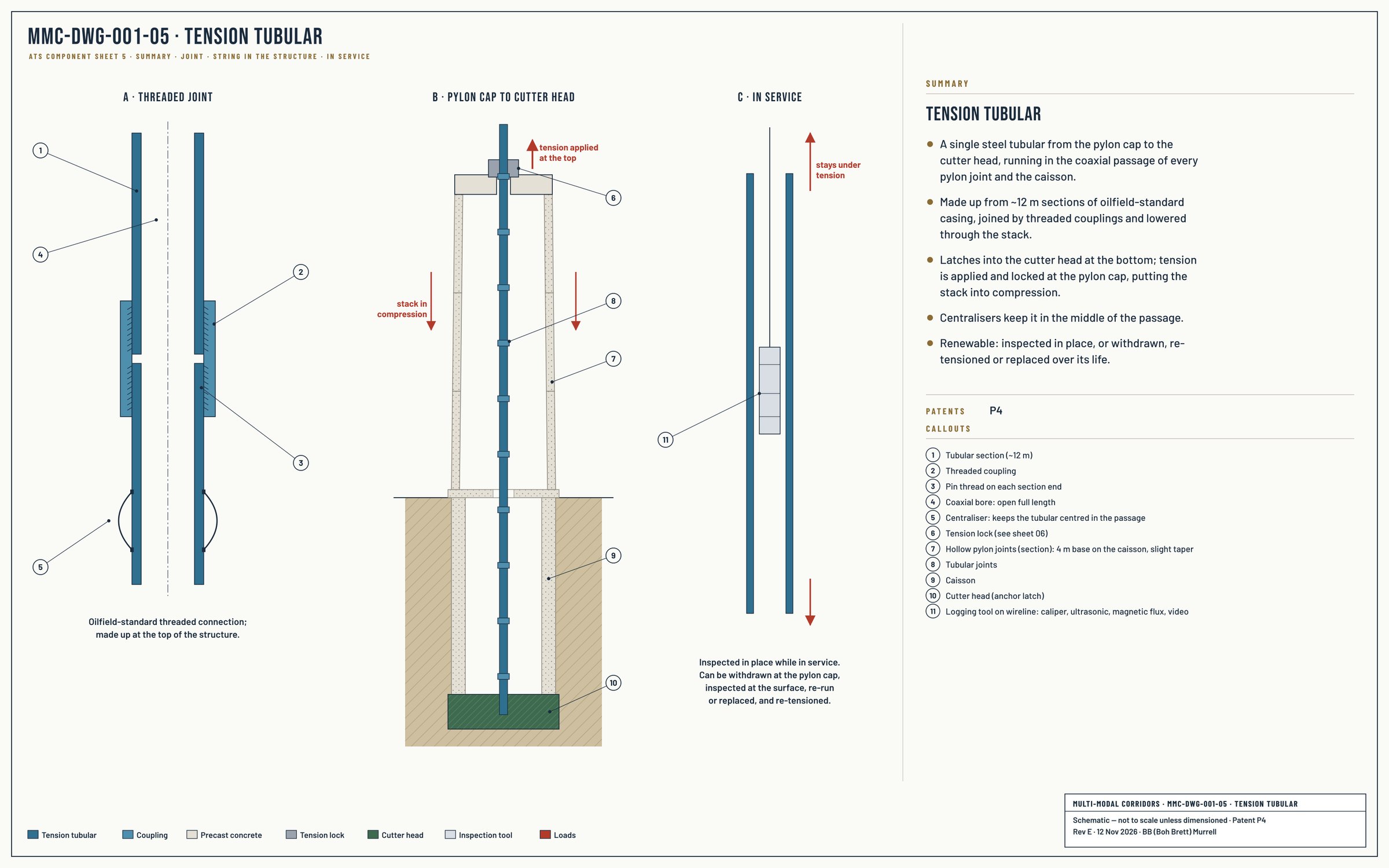
The renewable architecture is the operational consequence. Oilfield tubular strings are designed to be installed, serviced, inspected, replaced, and recovered through standard intervention practice. Applied to civil infrastructure, this gives ATS deployment a three-tier maintenance hierarchy. The tubular can be inspected in place using standard oilfield logging tools — caliper, ultrasonic, magnetic flux, and video inspection equipment, lowered through the tubular without withdrawing it, the structure remaining under tension and in service. Where in-place inspection indicates more thorough assessment is warranted, the tubular can be withdrawn through standard hydraulic intervention at the pylon cap, inspected at surface for corrosion, fatigue, or wear, then reinstalled. Where inspection indicates end-of-life, the tubular is replaced with a fresh element and the structure is re-tensioned. The pylon segments, the foundation, and the cutter head anchor are designed for the full operational life of the deployment without replacement; the inspectable tubular element refreshes on a condition-driven cycle rather than a time-driven schedule.
MMC-DWG-001-05 · Tension Tubular. One tubular from cutter head to pylon cap, in ~12 m threaded sections; inspected in place or withdrawn. Summary sheet, Rev E. Select to enlarge.
Patent 4 of the MMC Patent Family — Architectural Framework — protects the integrated architecture of pylon stack, captured topside elements, and tensioned tubular as a single structural system.
The ATS tensioning architecture scales by stacking tubular elements. A single tubular element provides engineered tensioning capacity sized to a baseline pylon configuration — adequate for distribution-pole-scale and most transmission-tower-scale deployments. For larger pylons — taller stacks, heavier topside loads, larger-diameter segments — the architecture supports stacked tubular configurations that multiply the available tensioning capacity within the same caisson and pylon framework.
The principle is direct: more tubulars in parallel = more tensioning capacity = larger structures supportable on the same architectural primitives. A continental multi-modal viaduct carrying maglev passenger service, three electrified freight tracks, HVDC transmission, and utility lines on a multi-deck topside requires substantially more tensioning capacity than a single transmission tower carrying a few conductors. The ATS architecture provides this scaling natively through multi-stacked tubulars without requiring a different foundation methodology, different pylon segment manufacturing, or different construction practice.
The scaling principle is what makes the ATS truly platform-grade rather than configuration-specific. The same productised manufacturing system, the same drilling rigs, the same construction methodology produces every scale of deployment — the tubular configuration adapts the tensioning capacity to match the application.
Threaded Connections and Torque
Tubular connections draw on the threaded coupling engineering developed and refined for oilfield service — API-standard and proprietary premium thread geometries, codified makeup torque practice, established field service procedures. ATS connections are sized and specified for ATS load requirements, with the underlying connection engineering inherited from oilfield practice.
Materials and Corrosion Engineering
ATS tubular and component materials are selected for the civil deployment environment of each corridor — saline coastal, sulphide-bearing inland soils, dry continental, marine. Material selection draws on the oilfield tubular goods catalogue (carbon steel, low-alloy steel, corrosion-resistant alloy, clad-pipe configurations) as a reference for civil deployment material engineering, adapted to ATS-specific service conditions and operational life requirements.
Hydraulic Tensioners and Locking
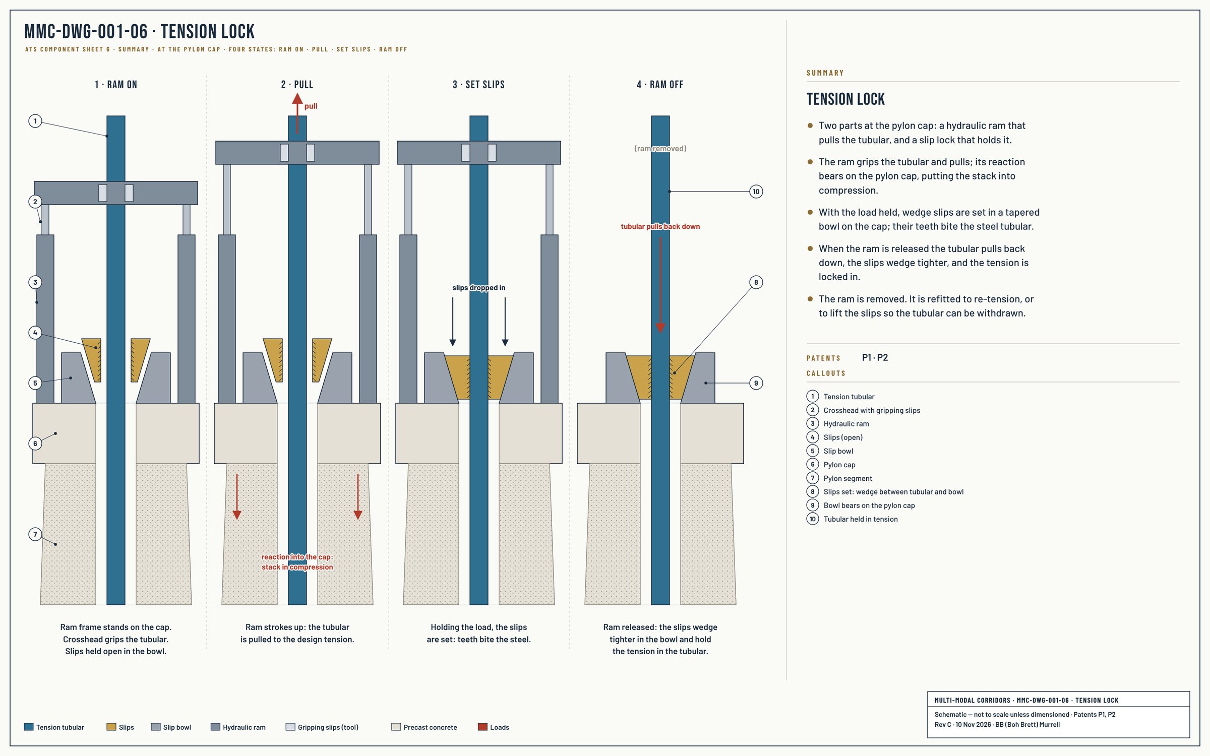
Tensioning the tubular involves two integrated elements at the pylon cap. First, a bespoke hydraulic ram system, purpose-engineered for ATS deployment, applies engineered tensioning load to the tubular. Hydraulic ram technology itself is mature, multi-vendor industrial engineering; the ATS tensioning system is the bespoke architecture assembled around proven hydraulic components for production-rate corridor deployment. Second, an engineered locking mechanism retains the tension once the ram is released — slips engaging the steel tubular, drawing on standard oilfield slip-on-steel engineering practice for tension retention. The locking mechanism is selected per deployment.
MMC-DWG-001-06 · Tension Lock. Ram pulls the tubular, wedge slips set in a tapered bowl, tension locked in. Summary sheet, Rev C. Select to enlarge.
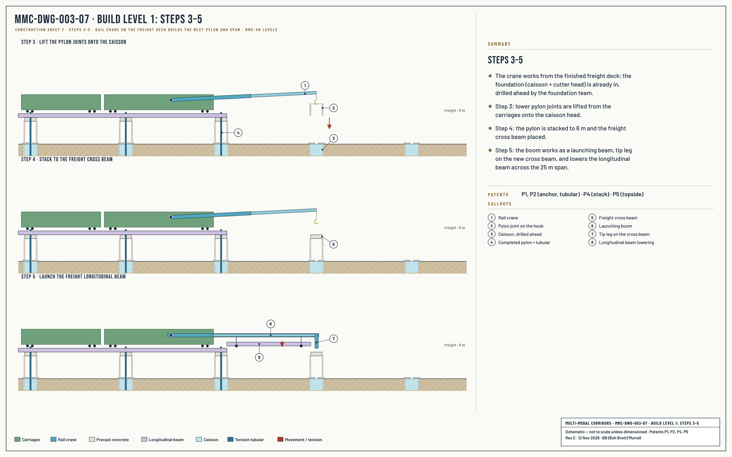
Pylon joints are lifted from the rail carriages onto the caisson head. The pin-and-box joints align each segment; the stack is dry-assembled, with no tubular yet.
The pylon is stacked to the height the terrain needs. A taller pylon takes more segments down the cone (002-07).
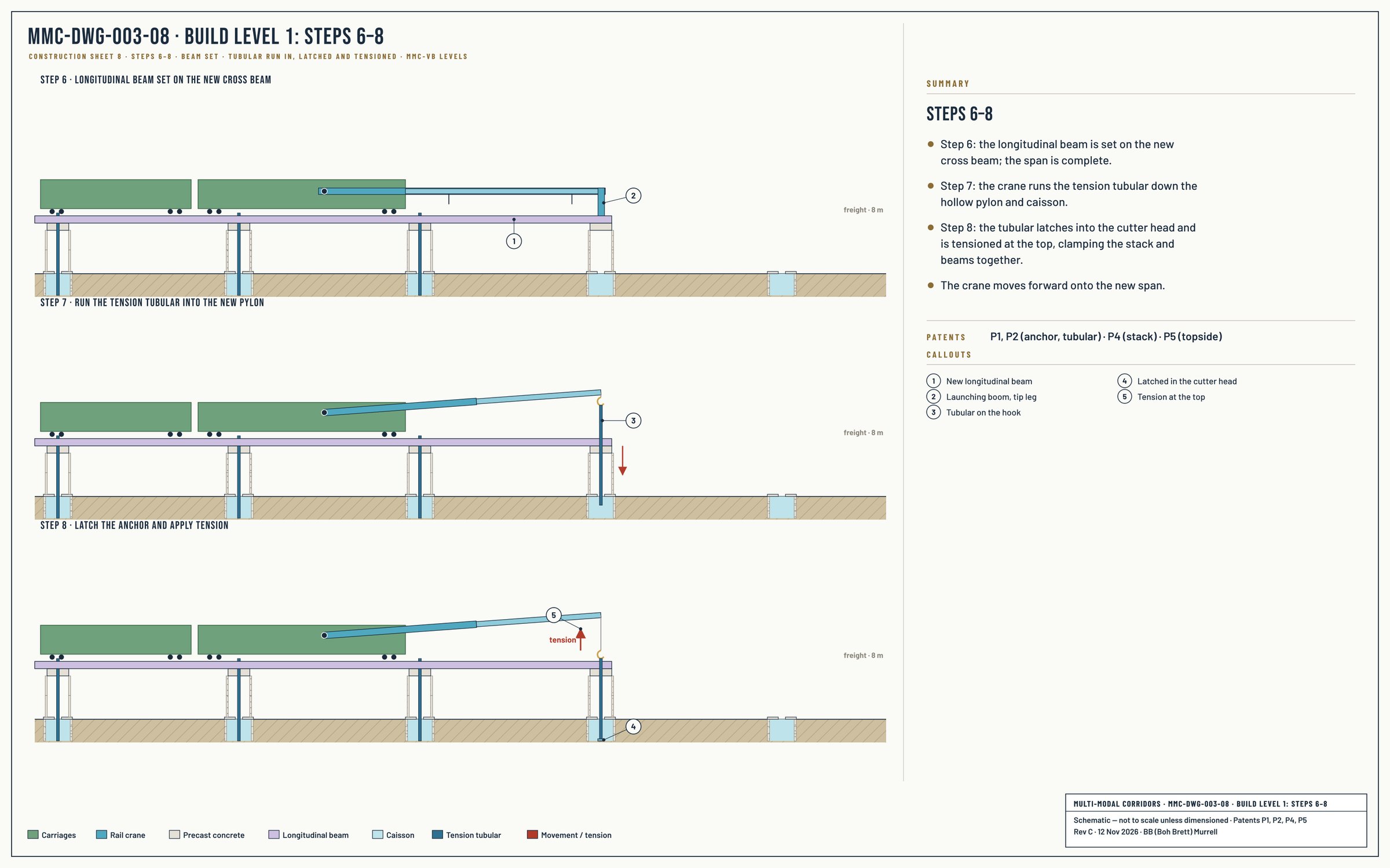
The tension tubular is made up at the top of the structure: a crane lifts each ~12 m section, and the sections are screwed together and run in, as on a drill rig, down the hollow pylon and caisson. On a viaduct this is done from the deck; on a tower, from a work platform at the top.
The tubular latches into the cutter head and is tensioned at the top, putting the stack into compression; the tension lock holds it.
MMC-DWG-003-07 · Level 1: Steps 3–5. Lift the pylon joints, stack to the cross beam. Select to enlarge.MMC-DWG-003-08 · Level 1: Steps 6–8. Run in, latch and tension the tubular. Select to enlarge.