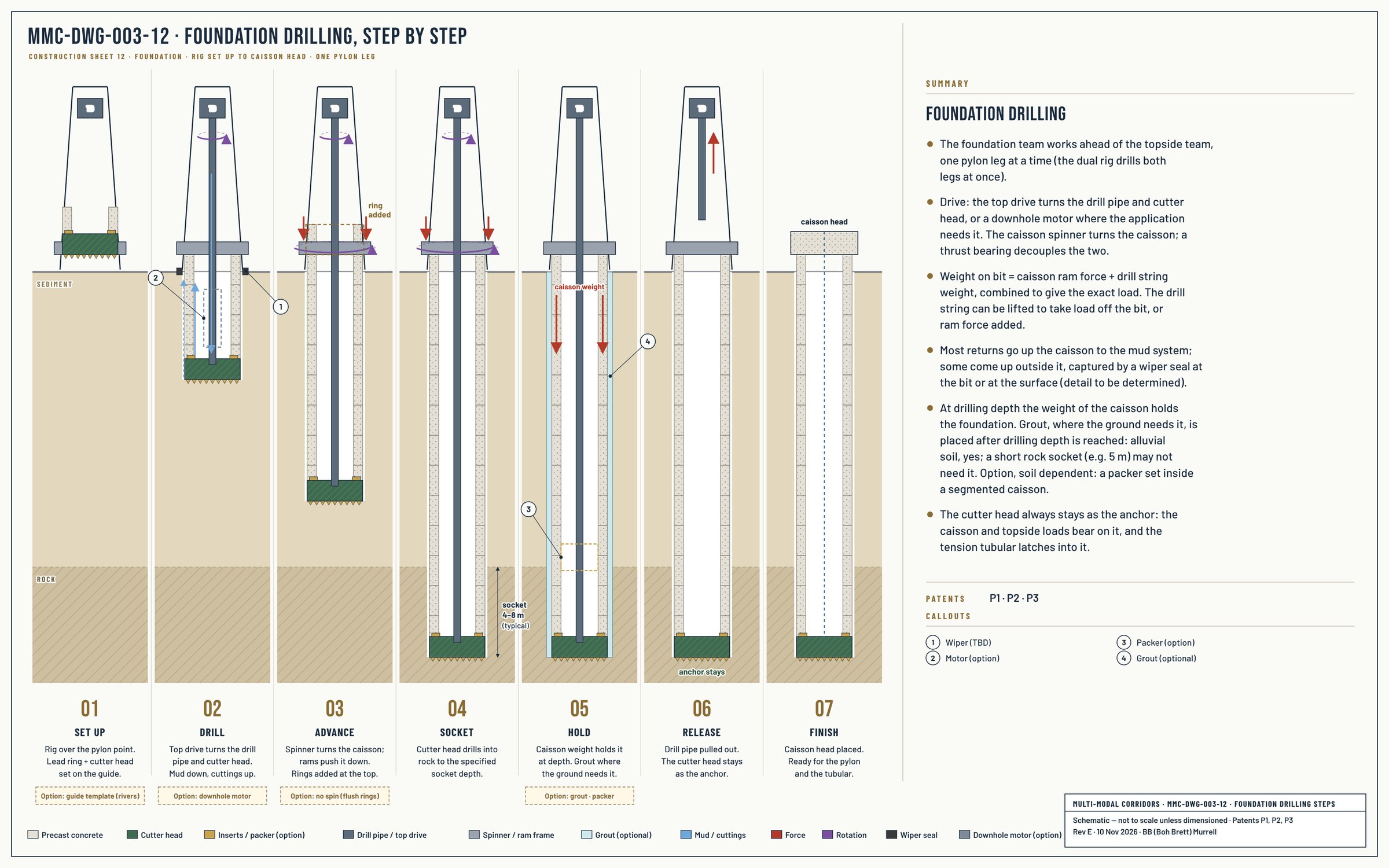
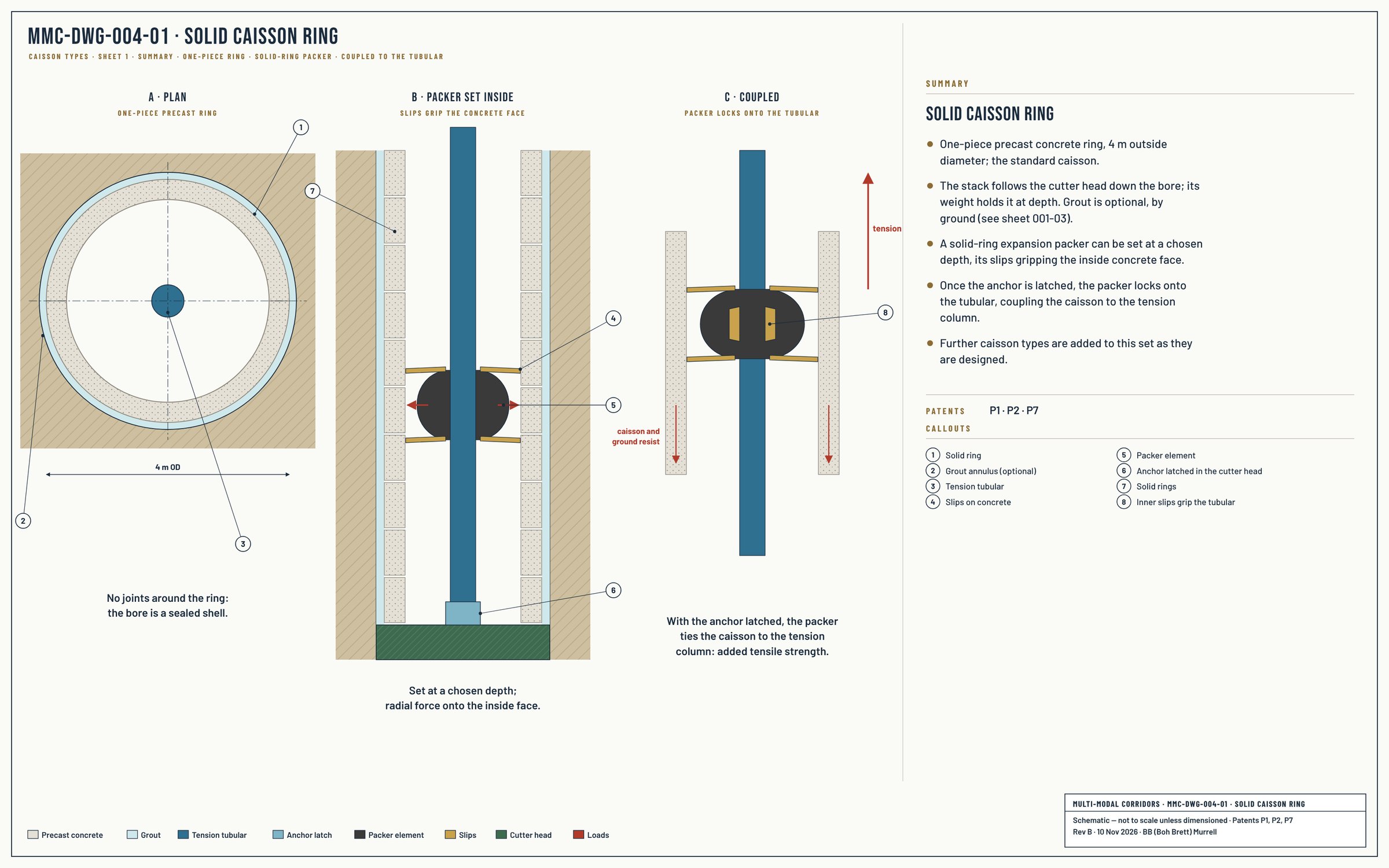
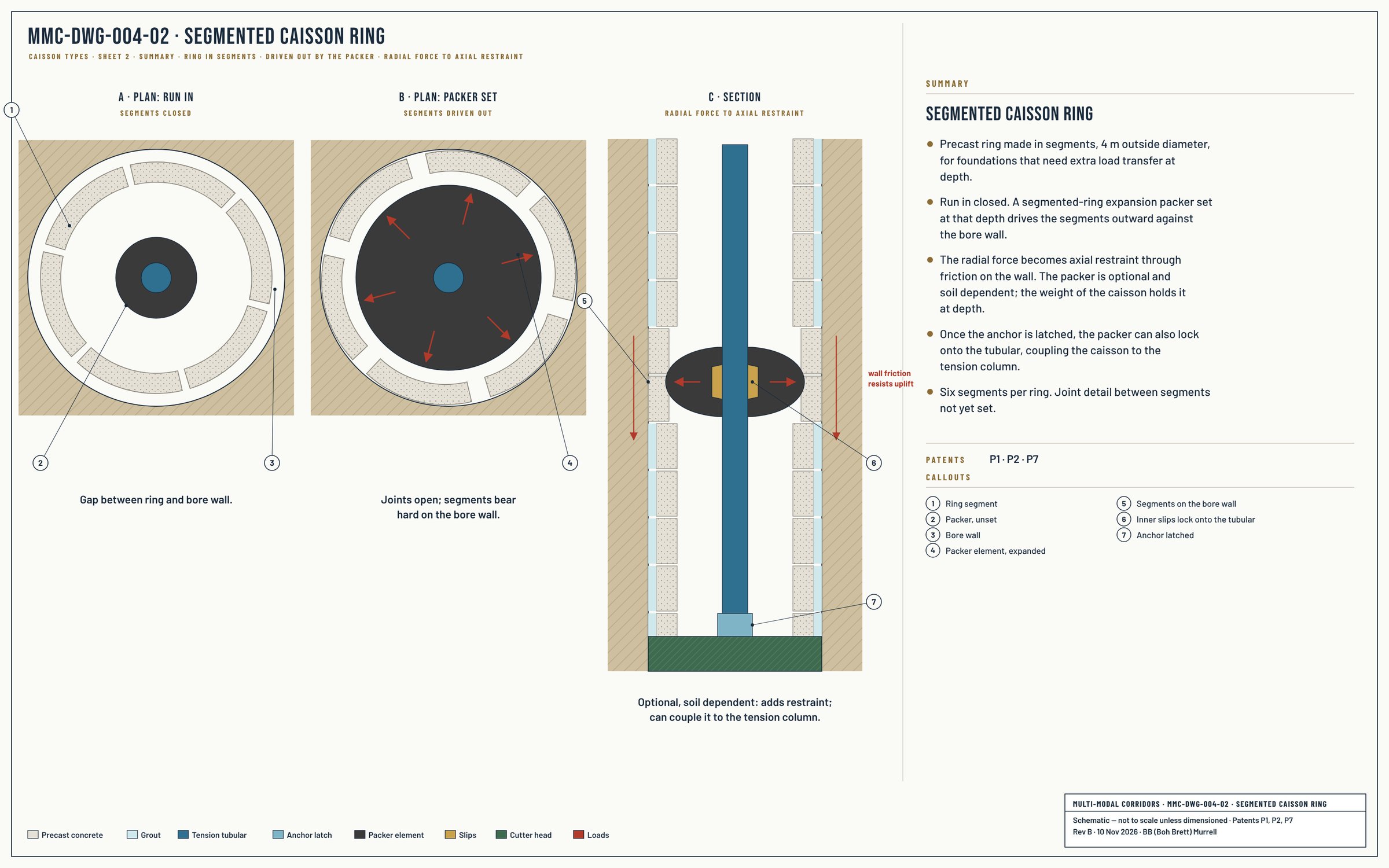
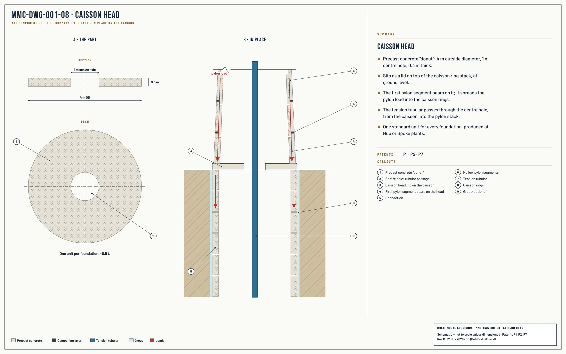
Every ATS deployment begins with a drilled caisson. A purpose-built drilling rig produces a vertical bore at the engineered foundation location, advancing through soil, weathered rock, or competent rock as the geology requires. At the engineered foundation depth, the cutter head — the specialised tooling at the working end of the drilling assembly — is detached and left in place. Where ground or loads need it, the caisson is grouted after drilling depth is reached, to bond the foundation core with the surrounding ground At drilling depth the weight of the caisson holds the foundation. A packer can be run and set inside a segmented caisson, soil dependent (option).
The cutter head, left in place at engineered foundation depth, becomes the foundation anchor — and the foundation load-bearing element. Its geometry is engineered to terminate the tubular tension column and to transfer both tension loads and the foundation's bearing loads into the surrounding ground at depth.
The caisson is installed as the foundation is drilled. The drilling rig advances the caisson, cutter head, and drill string as an integrated assembly to engineered foundation depth. When depth is reached, the cutter head remains in place; drilling and caisson installation are a single continuous operation, not two separate phases. This integration — disposable cutting head, anchor, and load-bearing element in one component, installed as part of the drilling operation itself — is a distinctive architectural feature of the ATS foundation.
The ATS caisson is precast in concrete rings, factory-manufactured in parallel with the pylon segments and drawing on the same regional precast manufacturing capacity. The caisson rings form the protective shell around the tensioning column, bond with the surrounding ground via grouting where it is used, and provide the sealed annular environment within which the tubular tension column operates. Segmental precast shaft and caisson architecture is established practice in deep foundation engineering and tunnel lining work globally.
The ATS caisson supports two configurations selected per deployment requirements. Solid precast caisson rings are used for standard ATS deployments — the baseline configuration providing the protective shell and ground bond described above. Segmented precast caisson rings are used for deployments that need extra load-transfer at depth. Segmented rings are radially-expandable — the caisson ring sections can be driven outward against the surrounding wellbore wall to convert radial force into axial load restraint. The segmented caisson configuration interfaces with the ATS service tooling architecture — particularly the packer and anchor systems described in the Service Tooling section below — with a packer, where the soil calls for one (an option), set at the segmented caisson depth to provide the radial expansion force; the resulting axial restraint either locks the caisson into the bore or couples the caisson to the tubular tension column for additional load support.
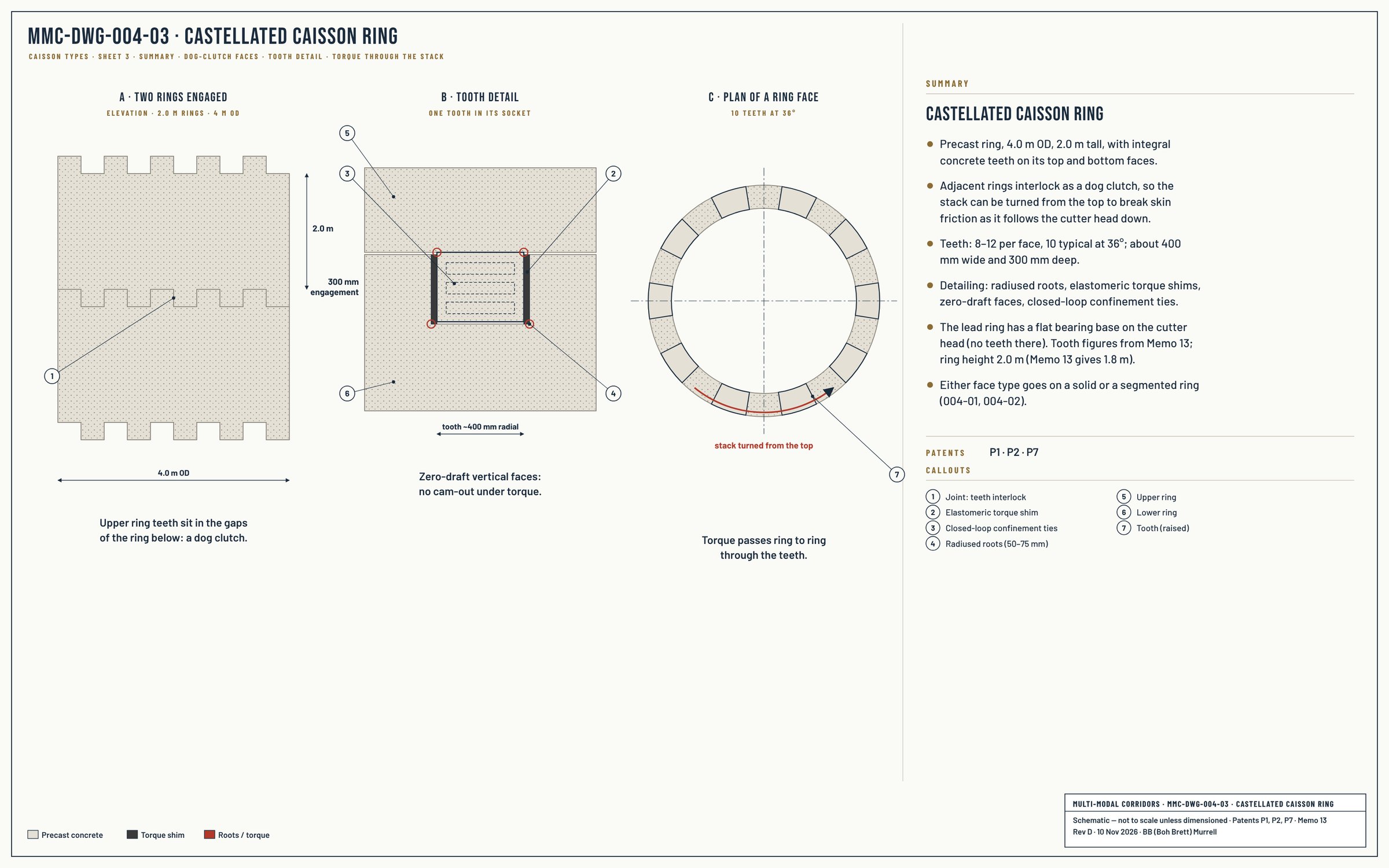
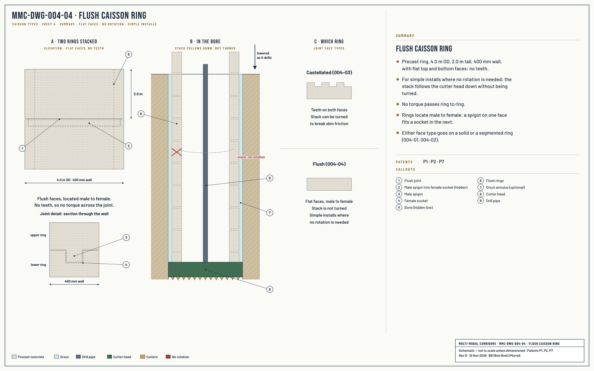
Both configurations use the same factory-cast precast manufacturing system, the same drilling and grouting methodology, and the same integration with the cutter head anchor at foundation depth. The choice between them is per deployment, based on the specific load and ground conditions of each foundation location. Ring faces come in two types: castellated, with teeth that lock ring to ring so the stack can be turned to break skin friction, and flush, with flat faces that locate male to female, for simple installs where no rotation is needed. Either face can be used on a solid or a segmented ring. Further caisson types will be added to this section as they are designed (drawing set MMC-DWG-004).
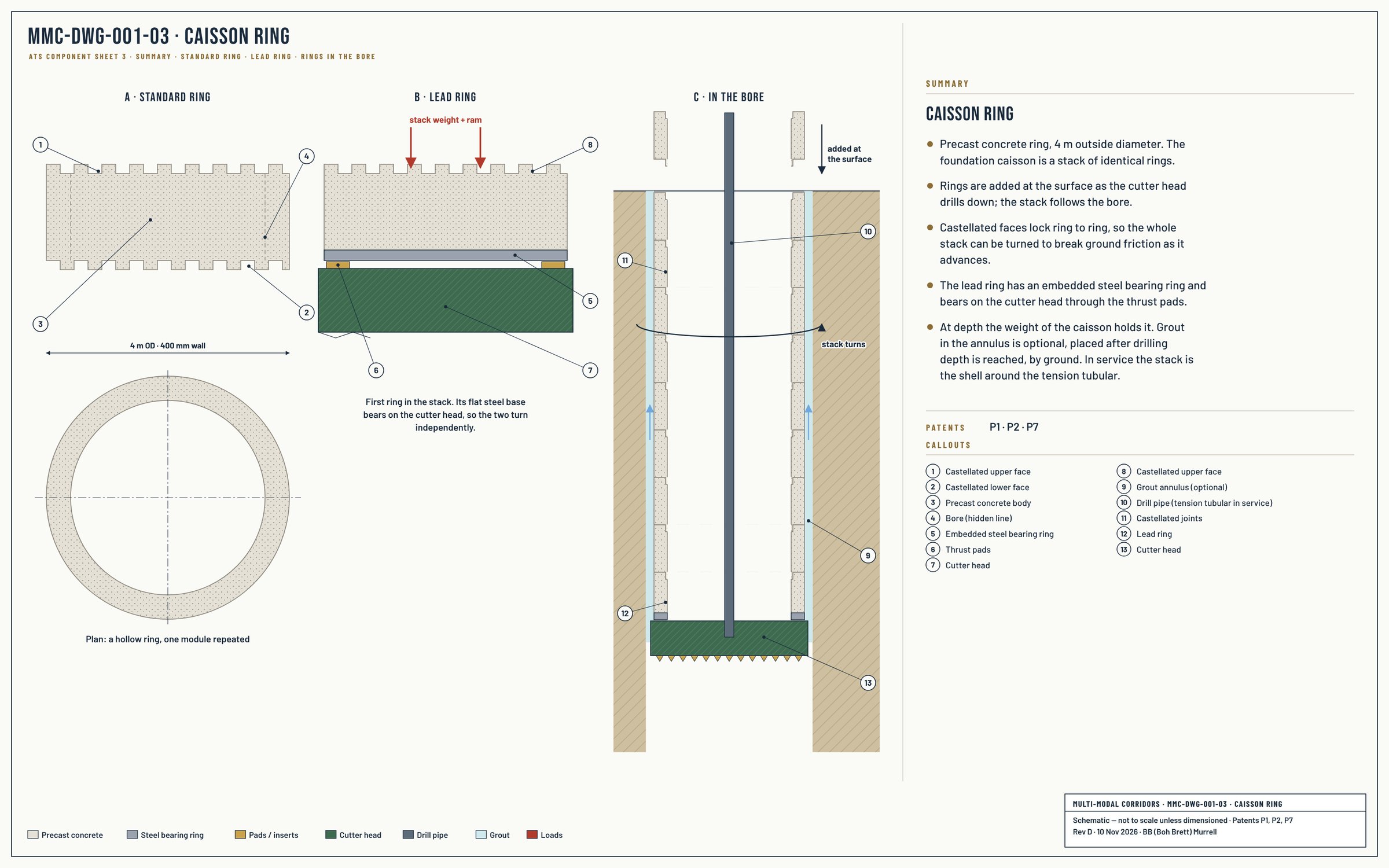
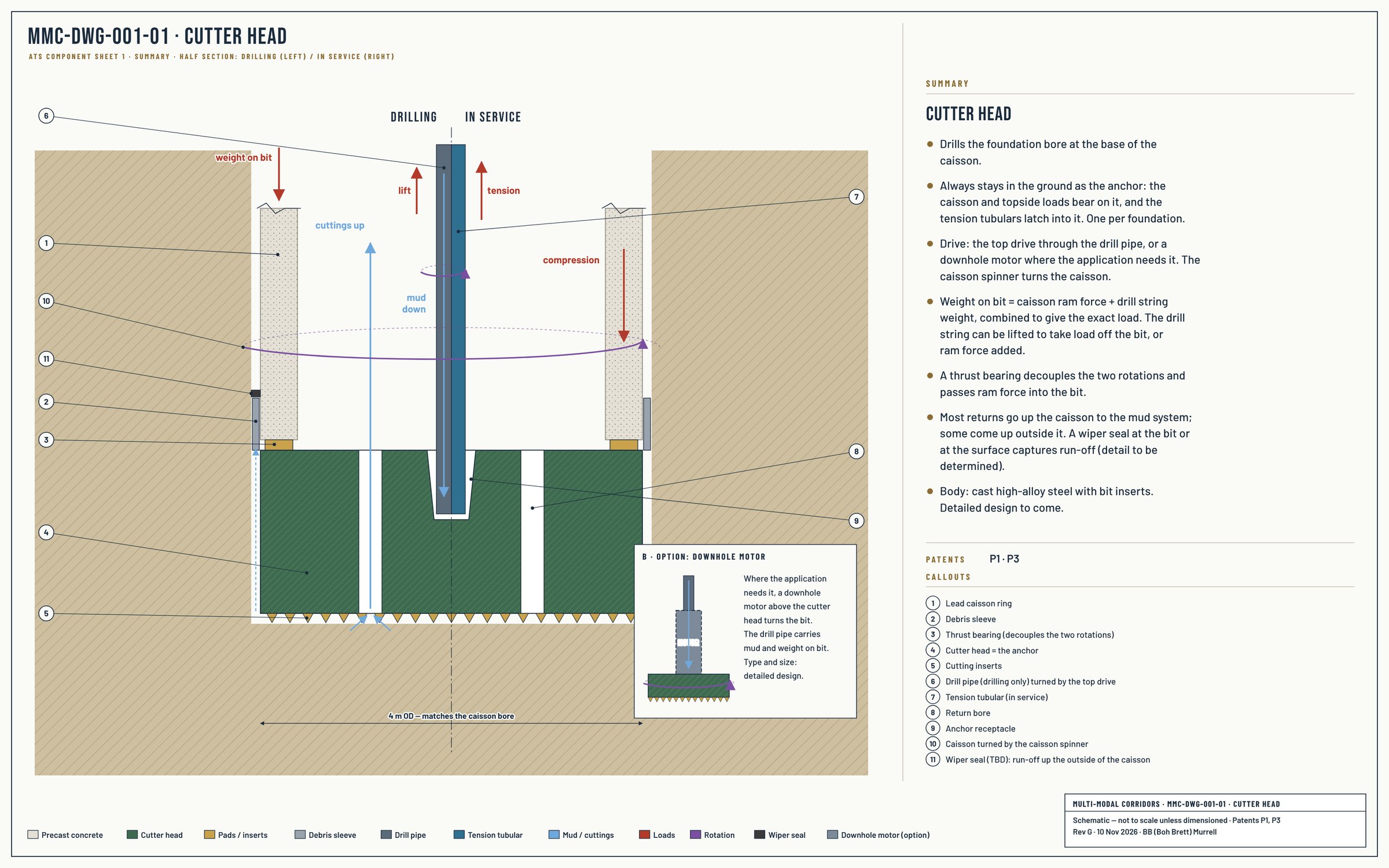
The ATS drilling rig is a purpose-built assembly comprising the drill string, the cutter head, the caisson, and a set of independent rotation and force-application systems at the drilling derrick. The architecture provides two independent rotation systems. The first is the drill string, which transmits torque from the derrick top drive down to the cutter head — the cutter head is driven by the drill string and rotates with it. The second is the caisson, rotated independently by a caisson spinner at the derrick. Hydraulic rams at the derrick apply downward force through the caisson body.
A thrust bearing arrangement at the caisson-to-cutter-head interface is the architectural element that allows the two rotation systems to coexist. A steel ring at the lower end of the caisson sits on the bearing in the cutter head; the bearing decouples the rotation of the caisson from the rotation of the cutter head while transmitting axial load between them. Downward force from the caisson body — caisson weight plus hydraulic ram force at the derrick — is transferred through the bearing into the cutter head and onward into the formation as bit-on-formation pressure. The cutter head can spin at drilling rate (driven by the drill string) while the caisson spins at a different rate (or remains stationary) to manage sidewall friction during advance.
The cutter head is driven by the top drive through the drill pipe, or by a downhole motor where the application needs it. Weight on bit is the caisson ram force plus the drill string weight, combined to give the exact load: the drill string can be lifted to take load off the bit, or ram force added. Most returns go up the caisson to the mud system; some come up outside it, captured by a wiper seal at the bit or at the surface (detail to be determined). The cutter head always stays in the ground as the anchor: the caisson and topside loads bear on it, and the tension tubulars latch into it.
The caisson rings are joined by interlocking sections between rings, allowing rotation transmission down the caisson stack from the spinner at the derrick to the lowest ring at the cutter head interface. The caisson functions as both the structural casing of the foundation and the rotating element of the drilling assembly — a single component serving two integrated roles.
During drilling, the caisson's own weight provides part of the bit-on-formation force, supplemented by the hydraulic rams at the derrick when additional weight is required. Caisson rotation reduces sidewall friction during advance, allowing gravity, hydraulic ram force, and mud circulation pressure to combine in driving the assembly to engineered foundation depth without sticking. The cutter head reaches depth, is disconnected from the drill string, and remains in place as the foundation anchor and load-bearing terminus.
Caisson drilling uses engineered drilling fluids — drilling muds — drawn from oilfield mud system technology. Drilling muds carry cuttings from the working face to the surface, maintain hole stability against ground collapse, cool and lubricate the cutting tooling, and provide the hydraulic environment within which downhole equipment operates. Oilfield mud systems are mature engineering practice with multi-decade operational experience across geology types, depths, and pressure conditions far beyond what civil caisson drilling requires.
The ATS adapts oilfield mud system practice to civil caisson drilling. Mud composition, circulation, solids control, and disposal use established oilfield equipment categories — mud pumps, shakers, desanders, desilters, mud tanks — adapted in scale to civil deployment requirements. As with the rest of the ATS service tooling, the architectural integration is novel; the underlying technology is decades of proven oilfield practice.
The drilled-and-grouted methodology with cutter head anchor is established practice in deep foundation engineering — used extensively in deep building foundations, marine pile installations, and earth-retention systems globally. What the ATS adds is the integrated architectural system: segmental caisson, disposable load-bearing cutter head anchor, and the oilfield mud system supporting production-rate deployment. This integration is protected by Patents 1, 2, and 3 of the MMC Patent Family — Foundation Core, Integrated Foundation, and Foundation Drilling System.
Foundation Core (P1) → Integrated Foundation (P2) → Foundation Drilling System (P3) →
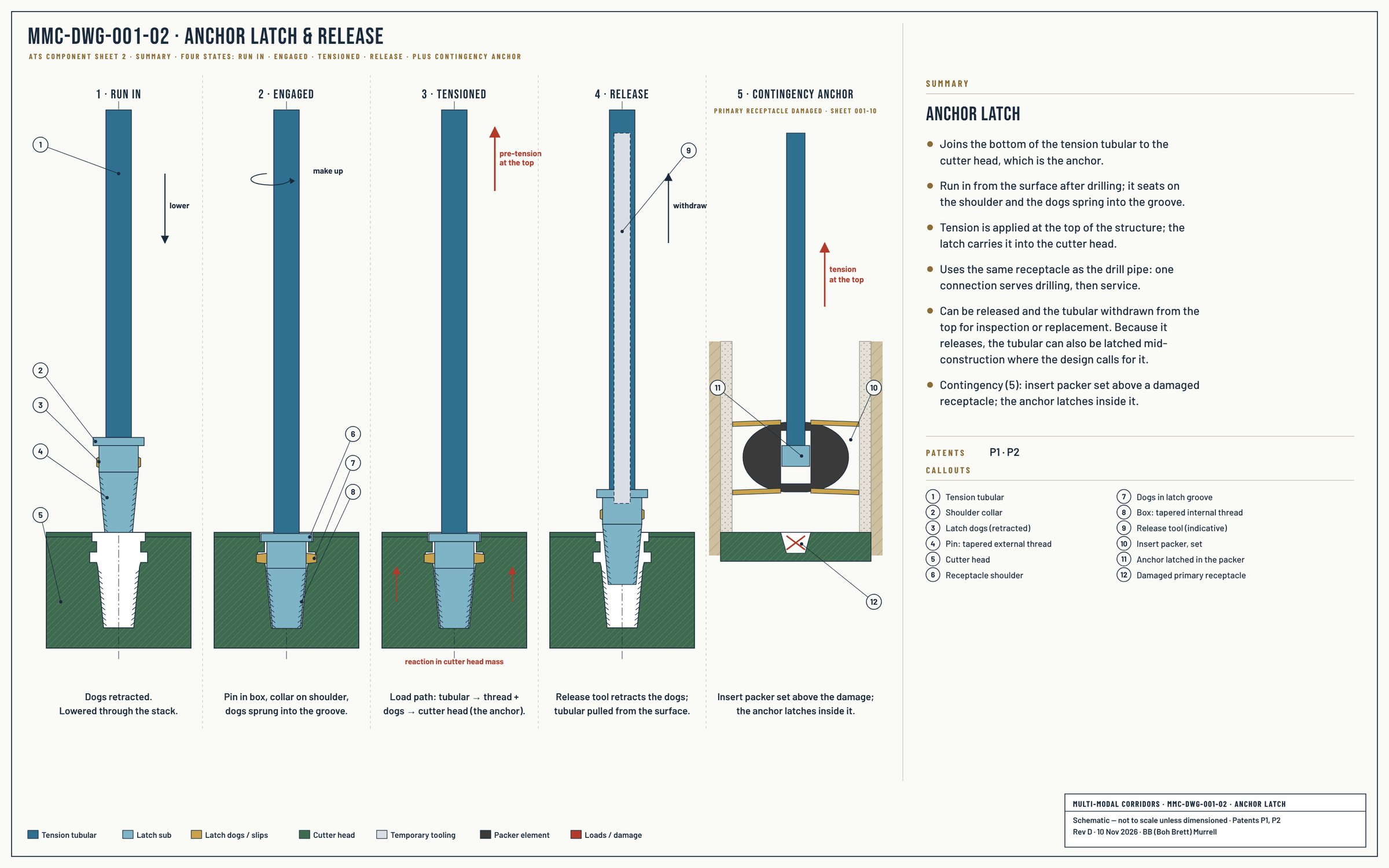
The cutter head anchor at foundation depth uses an engineered latch and release mechanism, drawing on the engineering category developed in oilfield completion practice for secure engagement and controlled release of tubular elements at depth. The ATS latch is bespoke equipment, engineered for the specific load requirements, geometry, and service environment of ATS deployment — not adapted oilfield hardware.
Tension is applied from the top of the structure. Because the latch can release, the tubular can also be latched mid-construction where the design calls for it. Contingency anchor: if the primary receptacle in the cutter head is damaged, an insert packer is run through the tubular hole and set inside the caisson; the tubular is then run in and its anchor latches inside the packer, so tension can still be pulled from the top.

Service tools used at the foundation (expansion packer, insert packer, centralisers): Service Tools & Equipment →
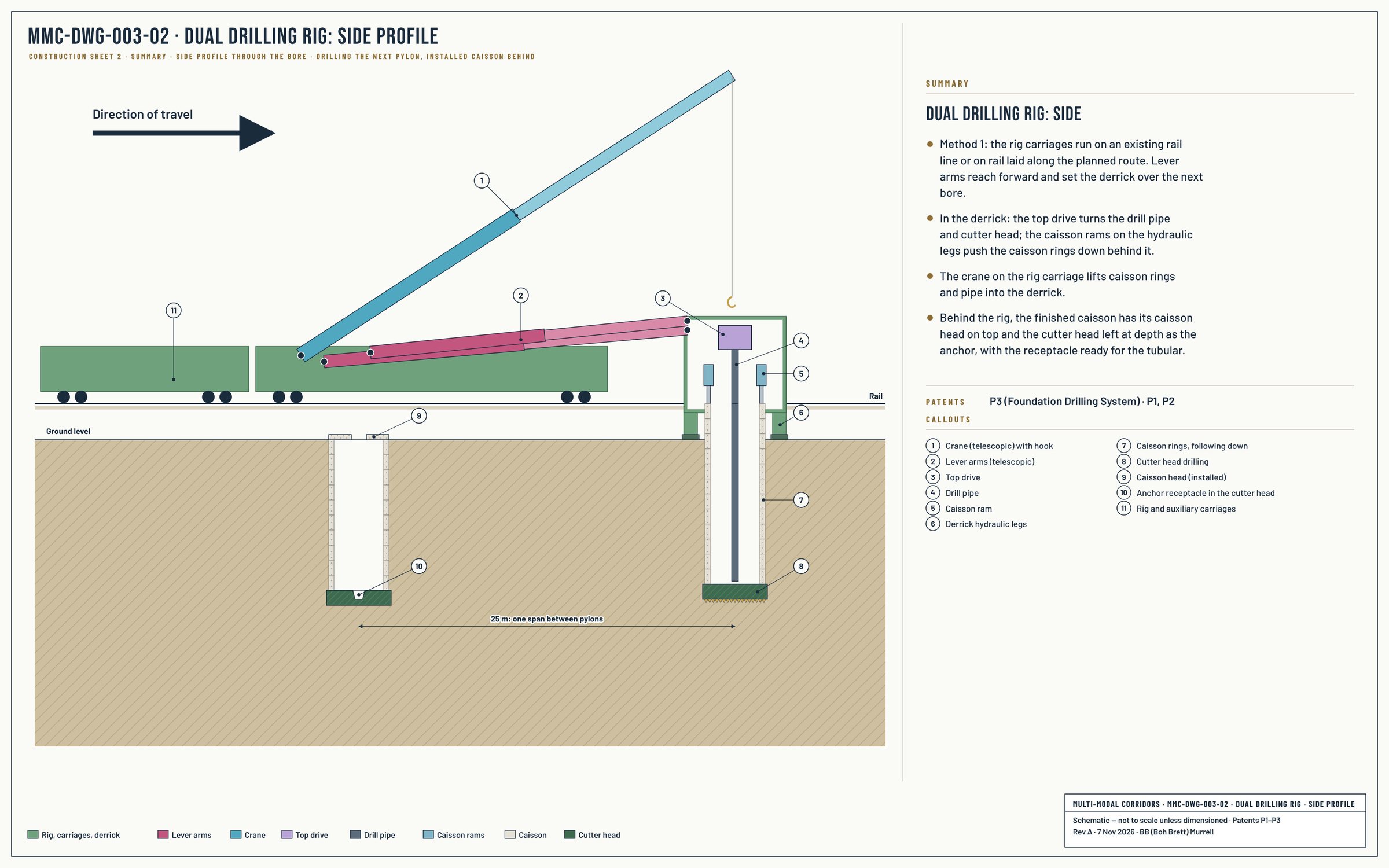
Each drilling rig drills the caisson bore, caisson rings follow the drill in sequence, and the cutter head is left at foundation depth as the permanent anchor. The rig moves to the next foundation and repeats. Multiple drilling rigs operate in parallel along the corridor; foundation production typically completes ahead of structural construction along the same segment.

Options, by application
Guide template (rivers) · downhole motor drive · packer set inside a segmented caisson, soil dependent · no caisson spin, with flush rings, where no rotation is needed · wiper seal at the bit or at the surface · grout after drilling depth, by ground (alluvial soil, yes; a short rock socket may not need it).
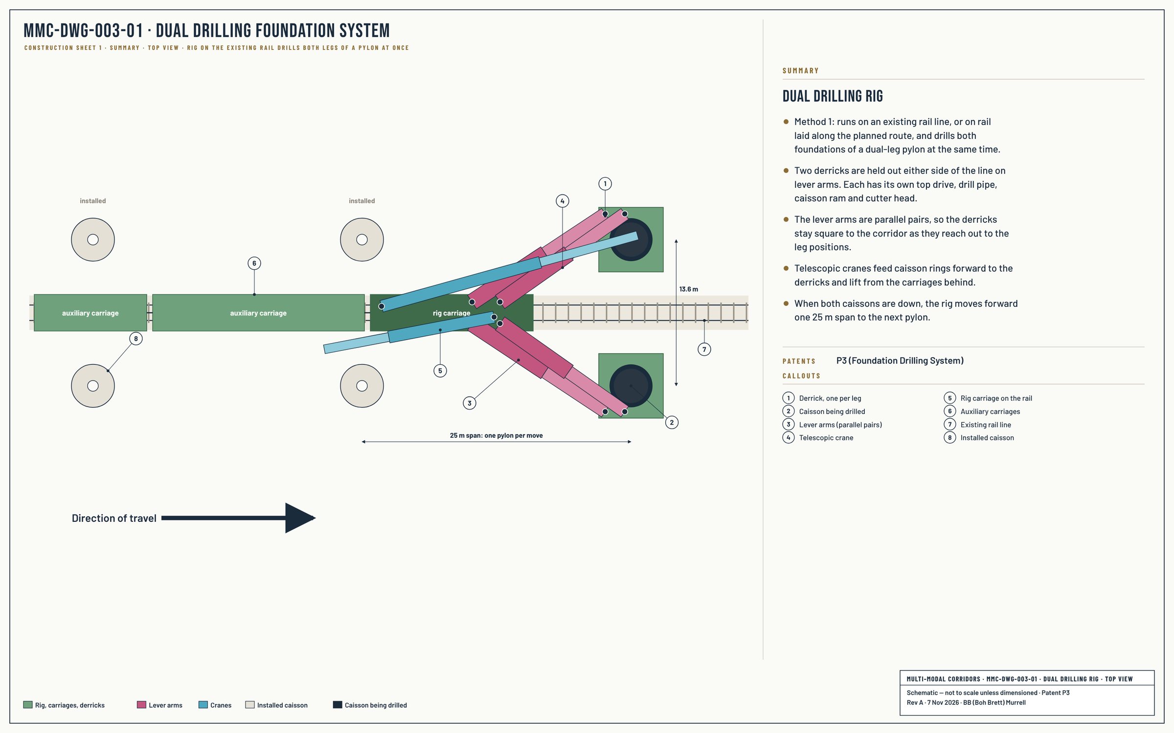
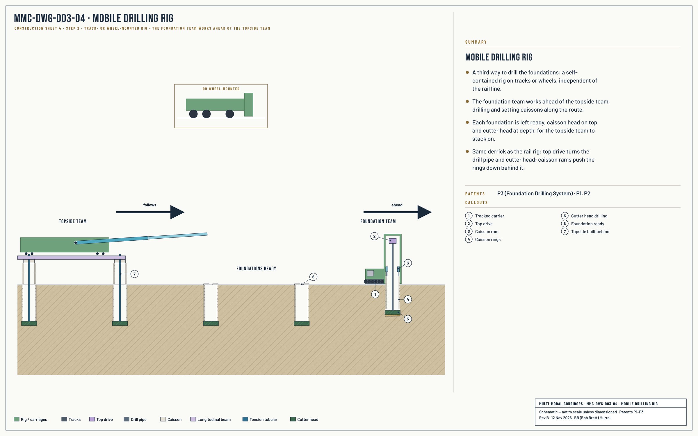
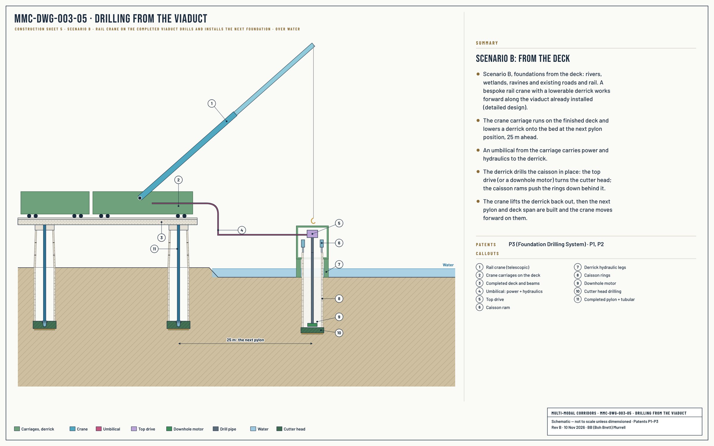
The foundation team works ahead of the topside team. Rail is laid along the planned route (or an existing line is used) and the dual drilling rig drills both legs of each pylon from the rail. Where rail is not practical, a track- or wheel-mounted rig drills ahead instead. Over rivers, wetlands and other difficult ground, foundations are drilled from the viaduct already built: the rail crane lowers a derrick to the next pylon position and drills it in place.
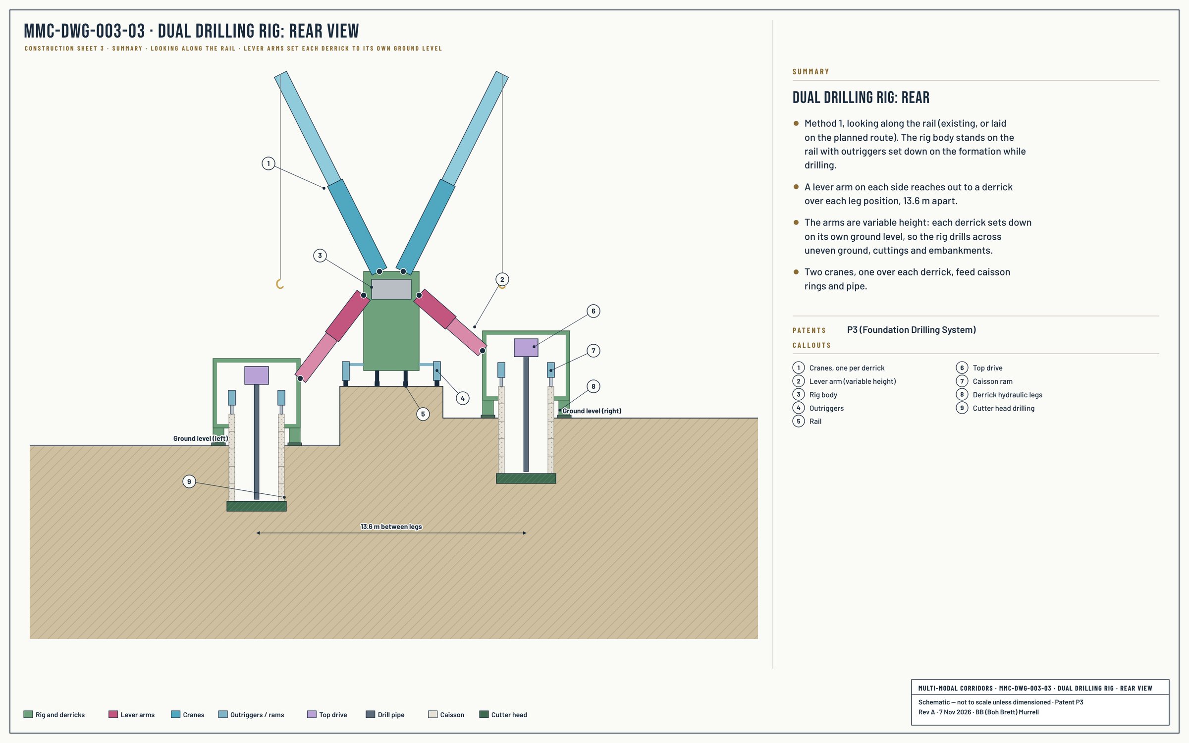
The dual drilling rig is the purpose-built rig that drills the two parallel foundations of a dual-leg viaduct configuration simultaneously, while operating over an existing rail corridor. The rig straddles the active rail line on outriggers, with two complete drilling assemblies (each with its own top drive, drill pipe, caisson ram, and cutter head) reaching out on either side of the rail to drill the viaduct's left and right foundations in parallel. The lever arm geometry is variable-height to clear overhead obstructions and accommodate different rail-corridor profiles.
This rig represents one of the platform's most distinctive capabilities. Conventional infrastructure expansion above existing rail corridors requires either acquiring new right-of-way alongside the rail, or extended rail outages while bespoke foundation work is conducted. The dual drilling rig makes neither necessary. Foundations for the dual-leg viaduct are drilled in parallel by a single rig operating over the rail; the rail continues operating (or runs with controlled short outages) during foundation production; the resulting viaduct adds passenger maglev, additional freight capacity, HVDC, and other MM Lines above the existing rail without taking new land. The rig is the engineering enabler for the platform's Phase 0 strategy of upgrading existing rail corridors rather than building entirely new alignments.


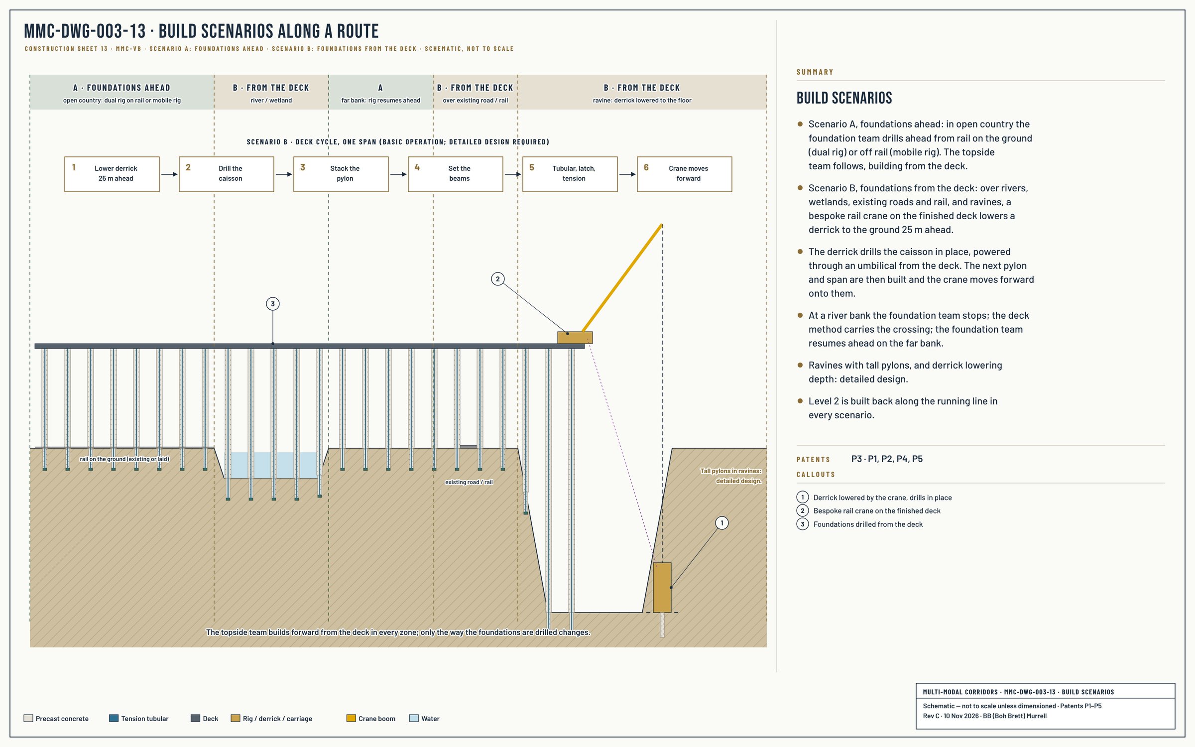
Where the foundation team drills ahead (scenario A) and where the foundations are drilled from the deck (scenario B):

Patent coverage: Patent 1 — Foundation Core · Patent 2 — Integrated Foundation · Patent 3 — Foundation Drilling System (AU 2026903869–2026903992) — caisson foundation, cutter head anchor, packer-set lock (optional), dual-leg drilling rig.