
MMC-DWG-001-01 · Rev B
Cutter Head
The cutter head drills the bore, then stays at depth as the sacrificial anchor.
High-level summary sheets: what each part is and does, not engineering detail. 33 sheets in four sets, Rev F, 7 November 2026.
Download the full set (PDF, 34 pages, 9 MB)The parts of the Anchor Tension System: cutter head, latch, caisson, packers, tension tubular, lock, riser and cap.
The cutter head drills the bore, then stays at depth as the sacrificial anchor.

The tubular latches into the cutter head receptacle: run in, engaged, tensioned, release; plus the contingency anchor seated in an insert packer.

Precast rings with castellated faces; the lead ring bears on the cutter head.

Two versions: segmented-ring (radial lock) and solid-ring (slips on concrete). Also centralises the tubular and locks onto it once the anchor is latched.

One tubular from cutter head to pylon cap, in ~12 m threaded sections; inspected in place or withdrawn.

Ram pulls the tubular, wedge slips set in a tapered bowl, tension locked in.

Hollow tapered segments, spigot-and-socket joints with a dampening layer, stacked to one continuous taper.

The donut lid on the caisson; the first riser segment bears on it.

Placed last; the tubular ends here and the tension lock bears on it.

Centraliser, anchor centraliser, and the insert packer that seats the contingency anchor.
The six named models and how one tapered segment family follows the terrain.

Single leg, single deck: cross-section and side elevation.

Two legs at the outer edges, freight beams on a 6 m pylon, maglev at 17 m.

Five levels; the aqueduct chute fills its bay.

Single-leg tower with a captured cross-arm.

Standard tower plus guy wires at 70% height.

Two pylons coupled by three captured cross-beams.

The same segments stack to suit the terrain.
How a corridor is built: foundation team ahead, topside team behind; level 1 forward, upper levels back.

Foundation team ahead, topside team behind; level 1 built forward, upper levels built back.
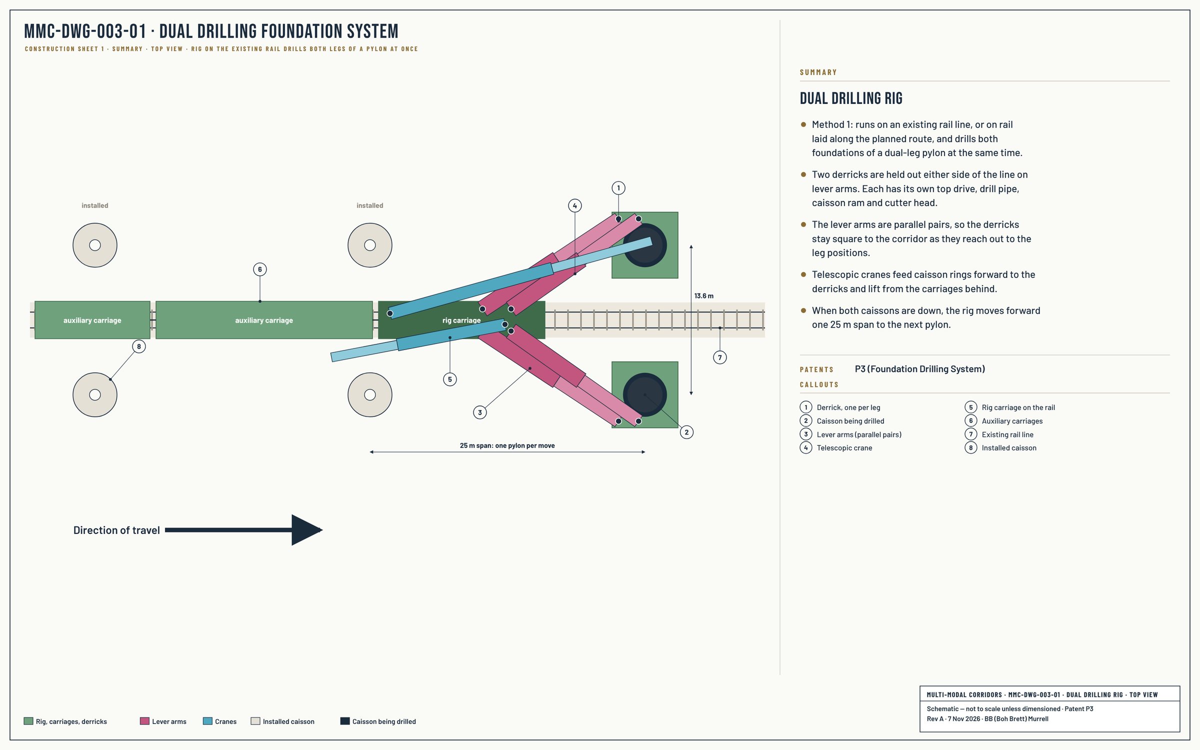
Method 1: the rig on rail drills both legs of a pylon at once.
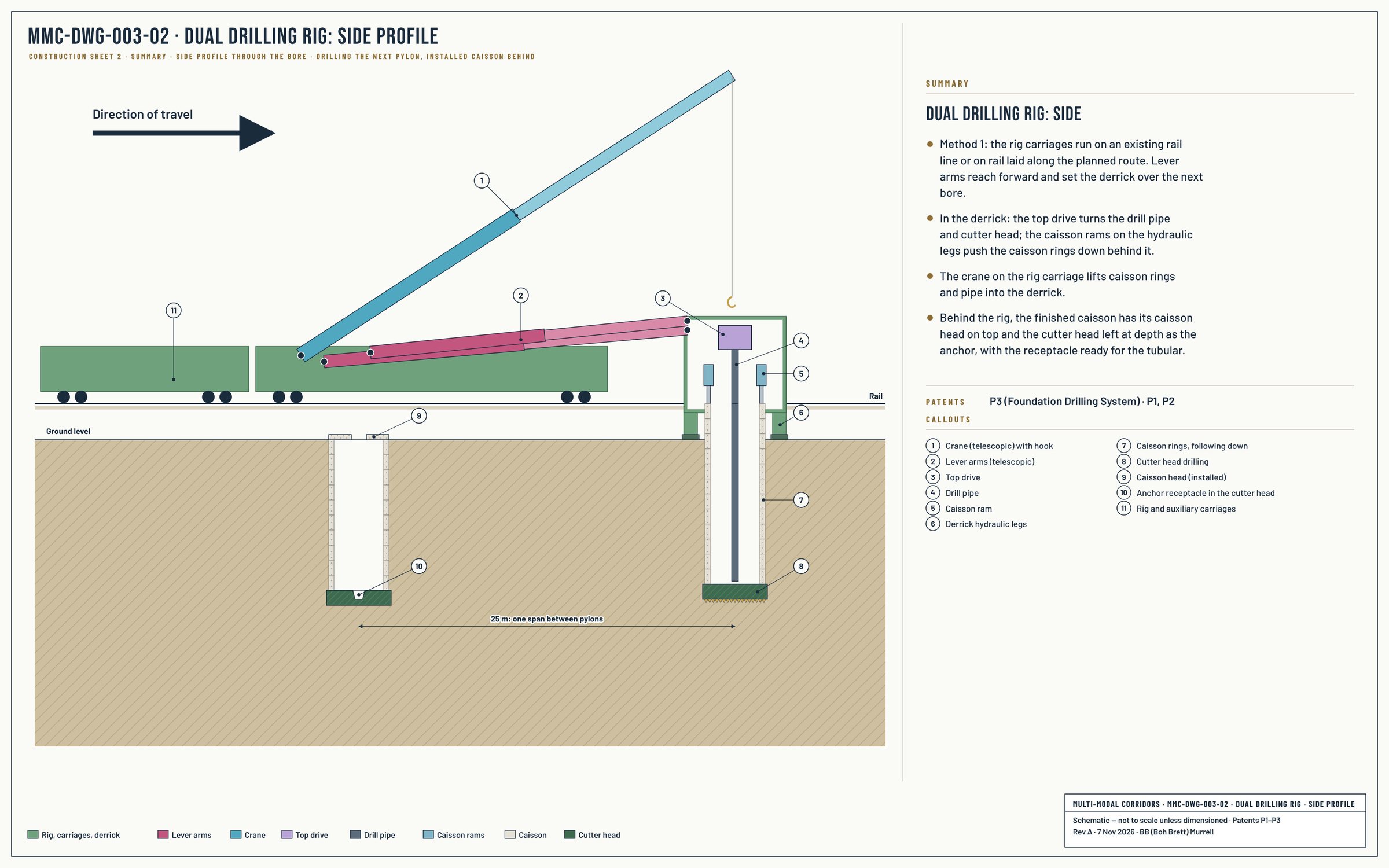
Top drive, drill pipe and caisson rams in the derrick; finished caisson behind.
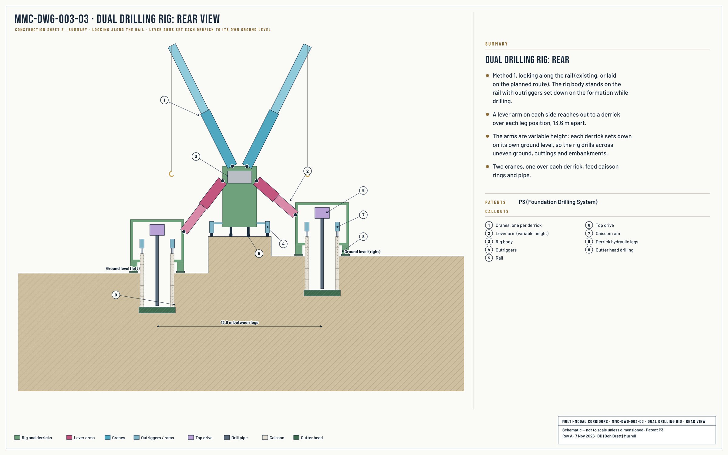
Variable-height lever arms set each derrick on its own ground level.

Track- or wheel-mounted rig; the foundation team works ahead of the topside team.

Method 2, for rivers and difficult terrain: drill the next foundation from the viaduct already built.

A ground crane builds the first spans; then the rail crane takes over on the deck.

Stack the pylon and cross beam; launch the longitudinal beam.

Set the beam; run in, latch and tension the tubular.

Level 1 runs the route; the crane comes back and withdraws one tubular at a time.

Stack the upper riser and maglev cross beam; lower the maglev beam.

Full-length tubular through both levels, latched and tensioned.
Caisson ring types: solid or segmented build, castellated or flush faces. More types are added as they are designed.

One-piece ring; the solid-ring packer sets inside it and, once the anchor is latched, locks onto the tubular.

The packer drives the segments out against the bore wall: radial force becomes axial restraint.

Teeth on both faces lock ring to ring like a dog clutch, so the stack can be turned to break skin friction.

Flat faces located male to female, no teeth: for simple installs where the stack is not turned.
Each sheet shows what a part is and how it works, with only the figures needed to read it. Where a figure is indicative rather than set, the sheet says so. The engineering behind each sheet is in the memos and patents.